Reducing cream cheese process waste via sanitary process control and inline recovery logic
Cream cheese plants lose edible, high value products when viscous cream-rich streams remain in trucks, tanks, unloading headers, flow panels, filler loops and CIP return circuits, then are displaced to drain during changeover or cleaning. The waste mechanism is rarely a single bad valve or a single operator miss; it is usually a control envelope gap where hold up is not quantified, product-water interface is not detected, and quality-protected diversion is not automated. This article presents a sanitary process control framework for reducing cream cheese-process waste through hold-up mass balance, controlled displacement, inline interface sensing, redundant totalized-volume limits, valve-proof permissive, documented governance and sanitation validation.
A representative dairy receiving case shows how 1.22 million lb/year of technically recoverable cream hold-up can be converted into an automated recovery opportunity, while a filler-loop magnetic-trap case shows how inspection redesign can prevent recurring product-to-drain losses and operator exposure. The same engineering logic is transferable across cultured dairy, yogurt, beverage and viscous food operations where edible product is lost at the boundary between production and cleaning.
The waste is usually hiding at the transition
In many dairy plants, the most expensive product loss is not the obvious spill on the floor. It is the product that still looks like food, still has value, and still sits inside a sanitary line at the exact moment production turns into cleaning. For cream cheese and cream-rich intermediates, that transition is unforgiving. The product is viscous, fat-bearing, aeration-sensitive and difficult to displace from horizontal runs, headers, manifolds, transfer hoses, pump casings, filler bowls and CIP legs. If the plant lacks a defined recovery sequence, the first meaningful displacement event often happens during rinse. At that point the product has crossed from food stream to drain stream.
The engineering opportunity is to move that boundary. Instead of accepting first-rinse loss as a sanitation cost, processors can recover edible product before it becomes waste. The method is not a shortcut around cleaning; it is an instrumented pre-cleaning step that confirms when product identity is still valid, routes that material to the food stream, and diverts once the product-water or product-air interface becomes uncertain. For dairy processors, this is where hygienic design, fluid mechanics, instrumentation and quality governance meet.
Why this matters beyond one plant
Food loss prevention is now a manufacturing responsibility, not only a consumer or retailer issue. FDA, USDA and EPA have identified a national goal to reduce U.S. food loss and waste by 50% by 2030. EPA also emphasizes prevention because much of the greenhouse gas burden from wasted food occurs before disposal, during production, processing, transport and distribution. For dairy processors, that makes product recovery before drain a direct sustainability lever: it keeps food in the human supply chain, reduces wastewater loading, cuts rinse demand and preserves the upstream energy already embedded in the product.
Cream cheese provides a strong example because small volumes translate into large annualized losses. A line that holds 80 lb and is cleaned twice per day can represent more than 58,000 lb/year before any filler bowl, valve cluster, truck heel or manifold loss is considered. The same loss physics applies to cultured products, yogurt bases, creamers, sauces and other viscous foods. That transferability is why the work should be treated as a process-engineering framework rather than a site-specific yield project.
Start with a loss boundary, not a solution
The first discipline is to define the loss boundary. Recovery projects fail when teams begin with a sensor purchase or a valve sketch before they know where product is actually being lost. A boundary should include the truck or tote heel, unloading hose, receiving header, transfer line, valve cluster, flow panel, surge tank, pump casing, filler supply loop, filler bowl, magnetic trap housing, static mixer, heat exchanger leg, dead-end branch and CIP return segment.
For each boundary, the engineering team should assign four attributes: whether the trapped material is edible at the time of recovery, whether it can be displaced without violating sanitary design, whether its identity can be confirmed by measurement, and whether the recovery route returns it to an approved food stream. A segment is a recovery candidate only when all four can be answered with evidence. This avoids the common trap of treating all hold-up as recoverable. Some material should go to drain because the interface is uncertain, the segment is not sanitary-recoverable, or the product identity cannot be protected.
Figure 1. Product recovery control envelope
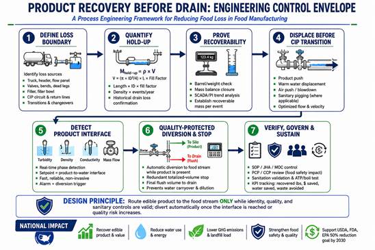
Figure 1. Seven-step engineering control envelope for recovering edible cream cheese or cream-rich dairy product before CIP transition. The sequence routes from loss definition to hold-up quantification, recoverability proof, displacement, interface detection, quality-protected diversion and governance.
Table 1. Loss-boundary map for cream cheese recovery
Loss boundary |
Primary loss mechanism |
Engineering calculation |
Recommended recovery method |
Quality safeguard |
Truck / tanker heel |
Residual cream after unloading |
Heel volume + hose/header inventory x density x deliveries/year |
Metered warm-water push or controlled air/N2 purge |
Turbidity diversion + totalized water limit |
Receiving header and transfer line |
Long-run hold-up in horizontal piping, low points and valve clusters |
Pipe volume + fitting equivalent volume + fill factor |
Water push or pigging for constant-diameter runs |
Inline phase sensor and route proof |
Flow panel / valve manifold |
Small volumes repeated many times |
Valve cavity and panel-leg volume x events |
Short controlled flush to recovery route |
Fail-to-drain valve logic |
Filler loop / bowl supply |
Viscous product retained prior to CIP |
Line inventory + filler bowl residual + pump casing |
Pigging, pre-CIP purge or controlled product push |
PCP/CCP review and sanitation validation |
Mag trap / filter housing |
Manual bleed and trapped pressure during inspection |
Housing volume + bleed loss/check x checks/year |
Mag-check mode or redundant parallel traps |
Controlled depressurization and foreign-material control |
CIP return leg |
First-rinse product sent directly to drain |
Historian rinse flow x first-rinse product concentration |
Sensor-based drain closure or recovery tank routing |
Defined interface setpoint and final drain diversion |
Table 1. Representative loss-boundary map for cream cheese, cultured dairy and cream-rich product recovery programs.
Quantify hold-up as mass, not just volume
Once the boundary is defined, quantify hold-up. The basic pipe inventory is straightforward:  . For sanitary tubing, the calculation should be adjusted for fittings, valves, tees, eccentric reducers, flexible hoses, pump cavities and filter or mag-trap housings. The result should then be converted to mass using measured product density and annualized by event frequency.
For cream cheese and cream-rich products, fill factor matters. Lines may not drain as ideal cylinders, and air blows can channel above viscous product rather than sweeping it. Long horizontal runs, low points and valve clusters often retain more product than the operator expects. A good estimate uses three numbers together: calculated line inventory, actual event frequency, and validation by barrel check or mass balance. The purpose is not to build a perfect academic model; it is to separate material loss from opinion.
A representative receiving case
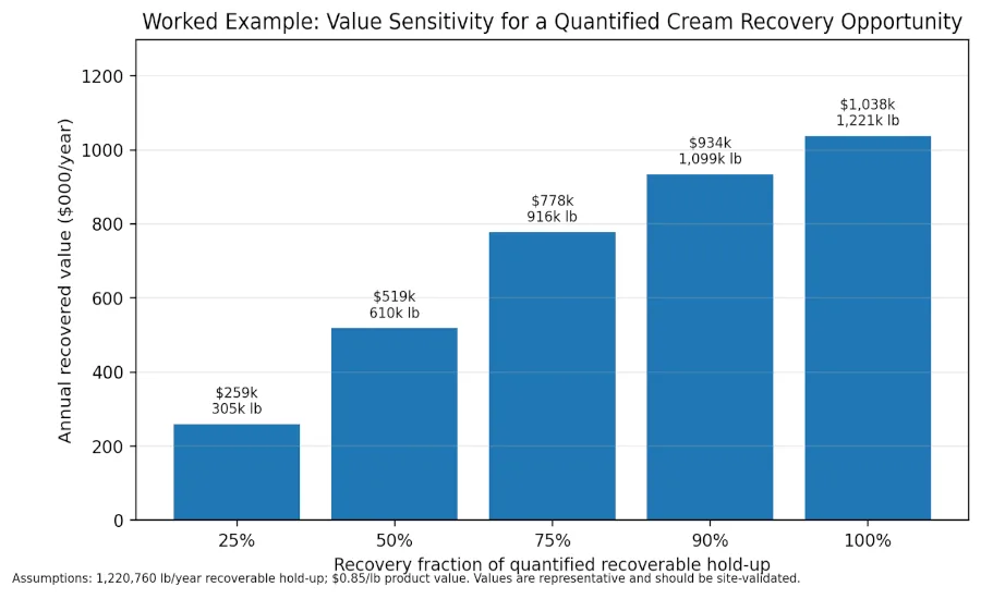
In a representative cream receiving system, yield records indicated 2.5 million lb/year of loss during truck unloading and transfer to cream silos. A boundary analysis separated total receiving loss from the recoverable fraction tied to truck heel, unloading header and transfer-line hold-up. The recoverable fraction was estimated at 1,220,760 lb/year. At $0.85/lb, this represented approximately $1.04 million/year of technically recoverable value. A conservative 90% recovery target produced an avoided-yield-loss target of about $934,000/year.
The important point is not the dollar amount. The engineering point is the proof mechanism. The opportunity was not claimed from a spreadsheet alone; it was supported by pipe-length calculation, event frequency, fishbone analysis and water-push trials where displaced material was collected and weighed. That is the standard dairy processors should use before automation: calculate the loss, collect the loss, weigh the loss, then automate only what has been proven recoverable.
Figure 2. Worked value sensitivity
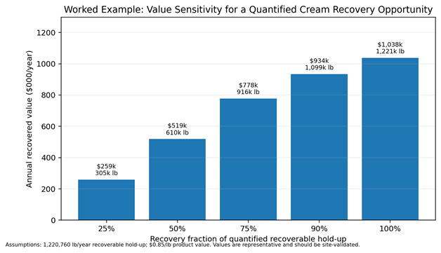
Figure 2. Worked value sensitivity using a representative quantified recoverable hold-up of 1,220,760 lb/year at $0.85/lb. Each site should substitute its own product value, event frequency and verified hold-up mass.
Displacement: water push, air purge and sanitary pigging
After recoverability is proven, the next question is how to move the product before CIP. Water push is often the simplest retrofit because the plant already has potable or process water, CIP routing and flow control. Warm water can displace cream-rich product from a receiving line or filler loop into an approved tank, but the design must prevent dilution. That means the water push must be metered, sensor-gated and bounded by a totalized-volume stop.
Air or nitrogen purge can be useful where water contact is undesirable, but it must be applied carefully in high-viscosity dairy. Air can channel, foam the product, disturb captured debris in a mag-trap area, or leave product stranded at low points. For long, constant-diameter runs, sanitary pigging remains one of the most effective technologies. Dairy Foods has previously reported that pigging is well suited to long product runs such as finished-product tank to filler bowl, and that a pig can clear around 99% of product between launch and receipt points. Pigging requires compatible piping geometry, unobstructed sanitary design, and appropriate launcher/receiver controls.
The best choice is usually not one technology for the entire plant. Receiving headers may benefit from metered water push and turbidity diversion. Filler supply lines may justify pigging or added pre-CIP purge points. Mag-trap inspection loops may require redundant parallel traps and controlled depressurization instead of product push. A good recovery program treats each loss boundary as a separate hydraulic problem.
Interface detection: the control point that protects quality
The critical control question is simple: when should recovered flow stop going to product and start going to drain? Time alone is a weak answer. Time assumes stable line volume, stable pump rate, stable valve response, stable product viscosity and stable operator setup. Dairy plants rarely behave that cleanly.
Inline interface detection is stronger. Turbidity is often well suited to dairy because fat and protein scatter light strongly while rinse water is optically clean. A turbidity transmitter installed in the recovery path can feed a 4-20 mA signal to the PLC, allowing the system to route flow to product while the reading confirms product and divert to drain when the signal drops through the validated interface threshold. Conductivity can help where ionic differences are strong, especially around rinse and chemical phases, but it may be less direct for cream-rich solids. Coriolis meters add value where mass flow, totalized mass and density are needed. Density can support interface confirmation, although the density separation between product and water may be narrow for some streams and temperature dependent.
For high-value cream cheese recovery, the strongest design is layered: turbidity or optical phase detection for identity, Coriolis or magnetic flow totalization for displacement limit, valve proof feedback for routing confirmation, and event logging for audit. No single measurement should carry the entire food-quality burden.
Table 2. Inline sensor selection matrix
Sensor |
Best use in dairy recovery |
Strength |
Limitation |
Typical control use |
Recommended role |
Turbidity / optical phase |
Cream-rich product vs rinse water |
Directly senses suspended fat/protein; fast response |
Needs clean optical window and validated threshold |
Switch product-to-drain at interface |
Primary interface detector |
Conductivity |
Rinse, chemical and water phase discrimination |
Robust and familiar in CIP systems |
Can be indirect for product identity; chemical carryover may bias reading |
CIP phase verification and secondary interface signal |
Secondary confirmation |
Coriolis mass flow / density |
High-value product totalization and density trending |
Mass and density data; good audit trail |
Higher cost; density gap may be small |
Recovered mass proxy and totalized stop |
Redundant protection and KPI |
Magnetic flowmeter |
Water-push volume control |
Reliable totalized volume for conductive fluids |
Does not prove product identity |
Independent injected-volume limit |
Safeguard stop |
Pressure transmitter |
Pump protection and route confirmation |
Detects dead-head, plugged line or low suction condition |
Not a phase sensor |
Permissive and alarm logic |
Reliability and safety layer |
Table 2. Sensor selection should be based on product identity, expected interface behavior, sanitation exposure and the consequence of a false product signal.
Quality-protected diversion logic
A recovery valve is not simply a valve. In this service, it is the boundary between food stream and drain stream. The control philosophy should be conservative and explicit. The default or faulted state should be drain, not product. Product routing should occur only when permissives are satisfied: route proved, receiving tank available, product identity confirmed, displacement volume below limit, pressure within envelope, and no active quality or sanitation alarm.
A practical PLC sequence is shown below in plain-language logic:
- Confirm recovery route is selected, receiving tank is correct, and valve positions are proved.
- Start metered displacement at validated flow and pressure limits.
- Route to product while interface sensor remains above the validated product threshold.
- Continue only while totalized displacement is below the calculated maximum plus validated margin.
- Divert to drain when interface threshold is reached, totalized volume is reached, valve proof fails, sensor signal is bad, or operator abort occurs.
- Record recovered mass proxy, injected volume, turbidity trend, valve state, alarms and operator acknowledgement.
- Release the line to normal CIP only after recovery completion and sanitation permissives are satisfied.
This is where process control supports food safety. The logic is not designed to maximize every last ounce. It is designed to recover product only while the evidence says the material is still suitable for the intended food stream.
Figure 3. Inline recovery logic
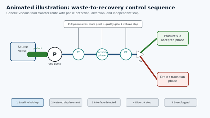
Figure 3. Typical animated sensor-gated recovery logic. The inline sensor confirms product identity while the totalizer provides an independent displacement stop. The diverter valve should fail to drain, not product, on instrument, valve-proof or control fault.
Mag-trap checks and filler-loop loss
Filler-loop inspection is another high-value area. In a representative whipped cream cheese loop, two sanitary magnetic traps served as the final physical barrier against metallic foreign material prior to filling. Manual inspection required a loop pause and depressurization through a small sample port, which created drain loss, rework, inspection downtime and splash exposure. At four checks per day, approximately 60 lb/check of product loss translated to about 84,000 lb/year. If inspection frequency increased to every two hours without redesign, the projected drain loss rose to approximately 252,000 lb/year, with substantial downtime.
The process-engineering response was not to reduce inspection rigor. The response was to redesign the inspection envelope. A mag-check mode can positively isolate each trap, provide controlled depressurization to an approved path, avoid manual sample-port bleeding, and restart the loop with fewer disturbances. A stronger configuration is redundant parallel mag traps with changeover valves and dedicated bleed paths so one trap remains online while the other is inspected. This is a good example of waste reduction and food safety reinforcing each other rather than competing.
Reliability is part of waste prevention
Pump reliability also belongs in the recovery conversation. Viscous cream cheese transfer systems can be forced into cavitation or dead-head operation when suction hydraulics, valve timing and permissive logic are weak. In a representative sanitary transfer network, frequent Axiflow pump failures were tied to lack of pressure feedback, valve-closure-on-running-pump events, operation below available NPSH at low tank levels, and restrictive suction geometry. The repair burden was not just a maintenance cost; it created unstable transfers, unplanned downtime and additional product-handling risk.
The corrective strategy was familiar to process engineers: add suction and discharge pressure feedback, prevent dead-head through valve permissives, enforce low-level speed logic, improve suction-side geometry, and trend events. When pumps stop damaging product and themselves, the line becomes easier to recover, easier to clean and easier to validate. Yield, reliability and sanitation should therefore be engineered as one control envelope.
Validation and governance
Recovery logic should be commissioned like a food-safety-relevant process change, not like a convenience feature. Validation should include dry I/O checks, water trials, product trials, barrel collection, product-quality checks, turbidity or density trend review, flow-totalizer verification, valve-proof failure testing, alarm response and sanitation verification. The team should document the maximum allowable displacement volume, interface setpoint, alarm setpoint, response time, drain-diversion margin and receiving-tank acceptance criteria.
Governance is equally important. SOPs must explain the recovery sequence and what operators should do when the system diverts early or faults. JHA/JSA documents should cover pressure release, hot water, chemical exposure, moving valves and sampling. MOC should update P&IDs, valve lists, instrument index, control narrative, cause-and-effect logic and training records. PCP/CCP reviews should confirm that recovery does not bypass a preventive control or introduce an unapproved rework path. Sanitation validation should show that the line still reaches the required cleaning conditions after recovery.
The KPI package should be simple: recovered lb/event, recovered lb/year, water push volume, early-divert events, sensor faults, drain loss proxy, CIP duration, rework avoided, and wastewater loading reduction. If the KPI cannot be trended, it cannot be sustained.
Table 3. Validation and governance protocol
Validation element |
Test method |
Acceptance criterion |
Record generated |
Hold-up estimate |
Pipe inventory calculation and barrel collection |
Collected mass reasonably matches calculated recoverable range |
Mass-balance sheet and photo/weight record |
Interface setpoint |
Product-water trials across expected temperatures and flow rates |
Repeatable switch point with conservative drain margin |
Trend overlay and setpoint approval |
Totalized stop |
Inject calibrated water volume and compare to meter total |
Meter error within site tolerance; stop before dilution risk |
Calibration / functional test record |
Valve proof |
Force route mismatch and failed feedback states |
System diverts to drain and alarms |
Cause-and-effect / alarm test sheet |
Sanitation |
Run full CIP after recovery and verify cleanliness criteria |
No loss of validated cleaning performance |
Sanitation validation record |
Food-safety review |
PCP/CCP/HACCP review of recovery path |
No bypass of preventive controls or unapproved rework route |
MOC and food-safety approval |
Table 3. Recovery logic should be validated as a governed process change, not only as a yield-improvement automation project.
A practical implementation roadmap
A robust rollout can be completed in stages. First, quantify and validate the largest loss boundaries. Second, automate one high-value route with simple sensor-gated diversion and totalizer protection. Third, add event logging and weekly exception review. Fourth, update SOP, sanitation and food-safety documents before declaring the sequence routine. Fifth, standardize the design into a repeatable template for other receiving lines, filler loops and high-viscosity product circuits.
The most effective projects are usually modest in hardware but disciplined in engineering. They use existing tanks, existing CIP infrastructure and familiar sanitary valves, but add the missing intelligence: measurement, permissives, route proof, fail-safe diversion and data review. That is process intensification at plant-floor scale - more food recovered, less water consumed, less wastewater generated and fewer manual interventions, without building a new plant.
Conclusion
Cream cheese process waste is not inevitable. Much of it occurs at predictable transition points where product remains in sanitary equipment but the plant lacks a validated way to recover it before CIP. By defining loss boundaries, quantifying hold-up, proving recoverability, selecting the right displacement method, detecting the interface inline and protecting diversion with conservative PLC logic, processors can recover edible product without weakening sanitation or food-safety controls.
The broader value is that the method is transferable. A cream cheese line, a yogurt line, a beverage line and a cultured-dairy receiving system may look different, but they share the same engineering problem: valuable product trapped between production and cleaning. Recovering that product before it reaches the drain is one of the most practical ways dairy processors can improve yield, reduce water and energy demand, lower wastewater burden and contribute to national food-loss reduction goals.
References and source notes
- Dairy Foods. Contact Us. Dairy Foods describes its editorial coverage as dairy news and information, technologies, trends, issues, in-depth features and expert technical articles for dairy processors. https://www.dairyfoods.com/contactus
- U.S. Food and Drug Administration. FDA, USDA and EPA Propose National Strategy to Reduce U.S. Food Loss and Waste. December 4, 2023. https://www.fda.gov/news-events/press-announcements/fda-usda-and-epa-propose-national-strategy-reduce-us-food-loss-and-waste
- U.S. Environmental Protection Agency. United States 2030 Food Loss and Waste Reduction Goal. Last updated December 4, 2025. https://www.epa.gov/sustainable-management-food/united-states-2030-food-loss-and-waste-reduction-goal
- Dairy Foods. Dairy plants use pigging systems to recover product, reduce waste. April 6, 2015. https://www.dairyfoods.com/articles/91078-dairy-plants-use-pigging-systems-to-recover-product-reduce-waste
- 3-A Sanitary Standards, Inc. 3-A Sanitary Standards and Accepted Practices for dairy and food-processing equipment. https://www.3-a.org
- FDA. Current Good Manufacturing Practice, Hazard Analysis, and Risk-Based Preventive Controls for Human Food, 21 CFR Part 117.
- Representative internal engineering source material: anonymized truck-to-silo cream recovery charter, mag-trap QC optimization concept, and sanitary pump reliability project summaries supplied by the author for technical examples.
Looking for a reprint of this article?
From high-res PDFs to custom plaques, order your copy today!